The CRAFS™ Alternative
Figures referenced in text below ... Put mouse on photo for Figure ID ... Click on Figure for Blowup View
To learn more about The CRAFS™ Alternative ... its technology, design, and applications … call : 770-461-3800 email: crafs.alternative@gmail.com
( See above Figures 1a-1b-1c-1d ; 2 ; 3a-3b-3c )
The CRAFS™ Alternative
Ever experience a sedimentation control project where the volume of retained sediment runoff was so great and the seepage rate of retained sediment laden fluid (SLF) through the Conventional Sediment Containment Systems (CSCS) was so slow that deep ponding of the SLF resulted upstream of the CSCS (e.g., silt fence) ? If so, you probably paid for costly repairs resulting from the unfiltered sediment runoff that flowed downstream due to overflow, knock down, or undercut of the CSCS. Are there alternatives to this CSCS that can stop these failures? Is there a sediment control system with the same filtration ability but a faster filtered seepage rate through the same flow path ? The answer is yes ... The CRAFS™ Alternative !
Conventional Sedimentation Control Systems (CSCS)
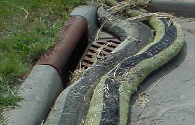
Silt fences, rock bags, fiber logs, and wattles are a few of the conventional sedimentation control system (CSCS) in use today. These and other measures are used to comply with Federal and state regulations requiring containment of sediment runoff within the boundaries of earthwork construction sites, and thereby preventing contamination of adjacent properties and waterways. (see Figures 1a, 1b, 1c & 1d)
These CSCS are installed across the flow path of sediment runoff in order to retain the SLF within identified boundaries of a construction site. While in its static state, the retained fluid of the SLF permeates through the sediment control system. The porosity and pore size distribution within the CSCS filter medium provides varying degrees of sediment retention while allowing minimal fine sediment particles to permeate through the system.
ASTM D6461 "Standard Specification for Silt Fence Materials" is often used on project specs to assure proper performance of aCSCS. Figure 1a and Figure 2 illustrate properly functioning "silt fences" as the CSCS provides its intended sedimentation control function on construction project sites. Other forms of CSCS may use a geotextile or mesh to encapsulate a mass of rock, polymer chips, etc (e.g., wattles), and the entire structure provides varying degrees of retarding the passage of sediment from the SLFpassing through it.
When properly installed and maintained, most of these “state-of-the-practice” sedimentation control measures provide “temporary containment” of the SLF that approaches the system. If retained by a silt fence, the SLF is held in a static state upstream of the geotextile lined fence structure. Much of the suspended sediments settle to the ground. And the geotextile retains the majority of solids that remain in suspension as the fluid slowly seeps through the CSCS and passes downstream.
Note that the primary objective for most CSCS used on earthwork construction sites is to provide compliance with government environmental regulations that require the prevention of sediment contamination to adjacent properties and/or waterways downstream. Those systems that comply with specifications such as defined in ASTM D6461 have proven effective for governmental regulation compliance under routine field conditions for decades.
Problems with Conventional Sediment Containment Systems (CSCS) Typical problems that lead to CSCS failures most often result from using the wrong CSCS for the field conditions present or improper (inadequate) installation. Both these problems can lead to a CSCS forced to retain excessively high volumes of SLF caused by high flow conventrations, channelized flow, high or multiple rainfall events causing large flow volumes into the CSCS, and/or localized grade changes in the terrain spanned by the CSCS (i.e., depressions in the ground surface adjacent to the system).
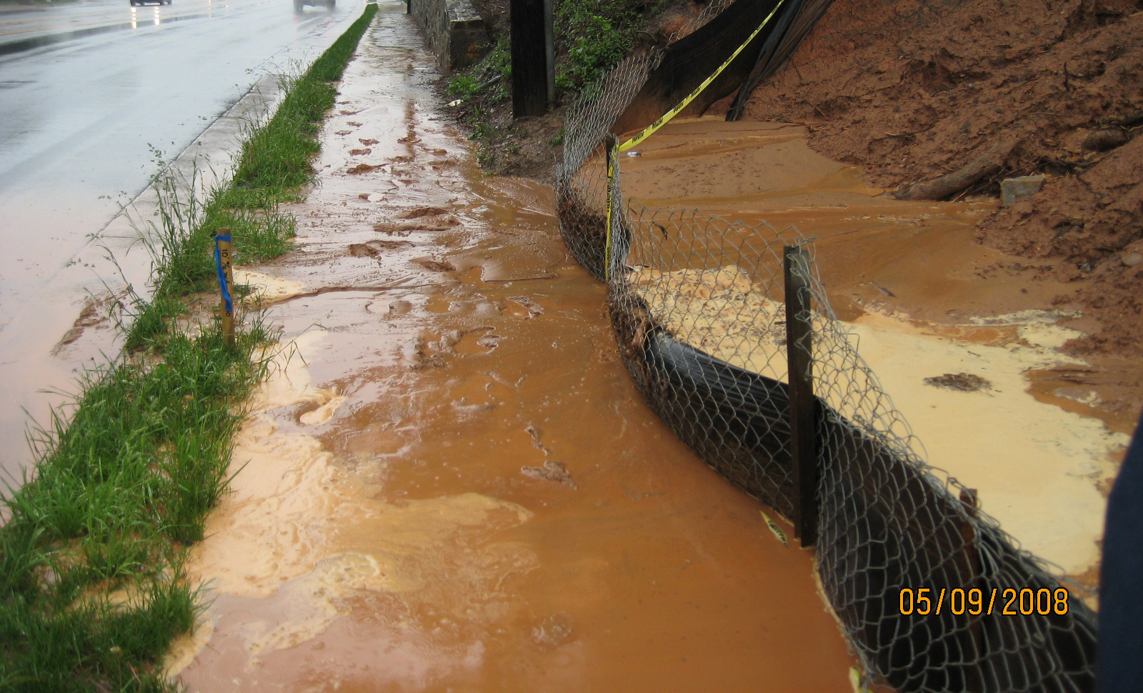
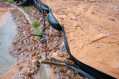
The result of these problems can lead to system failures, e.g., 1.) overflow of excess retained SLF, especially after subsequent flow events into a system that is already near full capacity, (see Figures 3a) 2.) total collapse of the system's vertical structure due to impact of the runoff or the prolonged lateral loads from the SLF retained, (see Figure 3b) and/or 3.) scouring, undercutting, and washout of the silt fence fabric's toe-in (i.e., burial at the base of the system) (see Figure 3c).
All these modes of failure are typically a result of the very slow rate of seepage of the SLF through the silt fence fabric of the CSCS. This very slow seepage results in prolonged ponding of the SLF upstream of the system. Even if installed properly, the structural elements of a CSCS (e.g., silt fence's vertical support elements, VSE) can become unstable and collapse when the subgrade becomes saturated for extended periods.
Numerous attempts have been made to accelerate the seepage rate of the retained SLF through the system by modifying properties of the system's geotextile. Modifications by increasing the geotextile porosity and permeability can increase the seepage rate through the system initially, but during the first event of SLF being retained, the seepage rate through the system is dramatically reduced by the retained solids on the upstream surface of the geotextile. The “retained solids” accumulate forming a “cake” of retained particles on the upstream side of the geotextile. As the cake of retained particles forms on the fabric surface, the seepage rate through the "modified" geotextile (with higher porosity and permeability) reacts just as it would through a conventional silt fence fabric on a CSCS, i.e. seepage rate decreases by an order of magnitude or more.
The CRAFS™ Alternative provides a viable solution to the problems often encountered by CSCS. A CRAFS™ is engineered by system design to provide a significantly greater rate of filtered seepage through the flow path spanned by the system. And the CRAFS™ provides much greater structural stability for resisting the lateral loads from the sediment laden fluid (SLF) it retains than a CSCS spanning the same flow path of SLF.
FASTER FILTERED SEEPAGE
CRAFS™ provides a more rapid rate of filtered seepage for the sediment laden fluid (SLF) it retains across a given flow path, i.e., sediment retention zone (SRZ). Comparative testing has been run on CRAFS™ and CSCS to confirm this claim. The filter medium on both systems is typically the same geotextile as specified for traditional CSCS (e.g., silt fence fabric), so the CRAFS™ filter efficiency is at least as good as that of the CSCS .
NO BLUNT IMPACT The CRAFS™ structure deflects the force of SLF flowing into it rather than taking the blunt impact of force from the SLF striking it head-on as does a traditional CSCS.
DIVISION AND DISTRIBUTION A CRAFS™ provides “division and distribution” of the SLF flow entering the system, spreading the SLF across a broader expanse of the retention system. This “division and distribution” 1.) reduces the stresses and forces acting on individual elements of the system, and 2.) isolates any potential failure zones and limits subsequent leakage of SLF through the system. The “division and distribution” limits the extent of possible system failures to a localized region of the system.
LATERAL LOAD SUPPORT BETWEEN THE VERTICAL SUPPORT ELEMENTS The vertical support elements (VSE) of the CRAFS™ provide lateral load support (LLS) to one another throughout the system and to the “retention-filtration-seepage medium” (RFSM) that spans between the VSE. LLS occurs throughout the CRAFS™ structure wherever VSE are connected by a RFSM. As a result, the CRAFS™ is able to support significantly more lateral load from the SLF it retains within the SRZ it spans than a CSCS spanning the same SRZ.
This LLS provided within a CRAFS™ makes it a more structurally stable system and less prone to failure due to collapse and/or overturning under lateral load from retained SLF than a CSCS.
FILTER CAKE CLEANSING
The engineering design of the CRAFS™ structure forces each flow event (after the first) to traverse downstream along the surface of the filter medium and wash off the particles retained (i.e., the filter cake formed) during the previous retention-filtration-seepage event. The result is a cleansing of the filter cake that was formed on the upstream surface of the system's filter medium during the “previous retention-filtration-seepage event”. This filter cake cleansing (FCC) action rejuvenates the system to a much faster rate of filtered seepage than it was capable of at the end of its “previous retention-filtration-seepage event” .
CRAFS™ DESIGN AND INSTALLATION The superior performance of a CRAFS™ versus a CSCS is a result of the engineered design of its corrugated structure following a state of the art patent pending process, with each system tailored for the specific field conditions and performance requirements of a given project site. As a result of its state-of-the-art technology, each CRAFS™ project should have an experienced CRAFS™ designer and installer involved ... to assess the system performance requirements, design and specify the appropriate structure for the site conditions, and install the system correctly to achieve the performance benefits offered by The CRAFS™ Alternative !
To learn more about The CRAFS™ Alternative ... its technology, design, and applications …
call : 770-461-3800
email: crafs.alternative@gmail.com
(See Figures 1a-1b-1c-1d; 2; 3a-3b-3c ... Below)
Figures referenced in text above ... put mouse on photo for Figure ID ... click on Figure for blowup view.